31+ memory controller block diagram
PERIPHERAL INTERFACE CONTROLLER PIC TAKE A LOOK. PWM1 is a pulse width modulator op-1.

Solar Charge Controller Using Microcontroller Block Diagram Block Diagram Diagram Electronics Projects
31 81 Parallel Interface Characteristics.
. For this reason later core systems combined the two into a single wire and used circuitry in the memory controller to switch the function of the wire. A function block is a program instruction unit that when executed yields one or more output values. 2x Ethernet interfaces2x 10100 Mbps Ethernet controllers.
To check a fuse look at the silver-colored band inside the fuse. The combination of both a new generation HBM2 memory from Samsung and a new generation memory controller in Volta provides 15x delivered memory bandwidth versus Pascal GP100 with up to 95 memory bandwidth utilization running many workloads. This is information on a product in full production.
Below we have a block diagram of DMA controller. Reset Enable and Reset Memory Timing. UP_LED is a USB good link LED indicator.
18 16 9 or 8-bit Bus 8080 Series MCU Interface 31 82 Parallel Interface Characteristics. The initialism NVM stands for non-volatile memory which is often NAND flash memory that comes in several physical form. Functional Block Diagrams.
NVM Express NVMe or Non-Volatile Memory Host Controller Interface Specification NVMHCIS is an open logical-device interface specification for accessing a computers non-volatile storage media usually attached via PCI Express PCIe bus. Functional Block Diagram FBD is a simple and graphical method to program multiple functions in PLC. The FlexLogix controller part of the Logix family of controllers provides a small powerful cost-effective system built on the following components.
FlexLogix controller that supports the Logix instructions. Throttle Actuator Control TAC Electronic Brake Controller. The fuse block access door is on the drivers side edge of the instrument panel.
P131 is a GPIO digital pin. The access time plus the time to rewrite is the memory cycle time. Transfer a block of data it instructs the DMA controller by sending the following information.
Direct Memory Access Diagram. The basic building block of PIC 16F877 is based on Harvard architecture. P00 is a GPIO digital pin.
January 2022 DS12991 Rev 4 194 STM32G030x6x8 Arm Cortex-M0 32-bit MCU up to 64 KB Flash 8 KB RAM 2x USART timers ADC comm. This microcontroller also has many advanced features as mentioned in the previous post. Voltas highly tuned 16 G HM2 memory subsystem delivers 900 Gsec peak memory bandwidth.
The Field Oriented Control FOC method described in this document is aimed at the growing market for cost-sensitive automotive drives such as fans pumps and geared motors. TAKE A LOOK. INTRODUCTION TO PIC 167F877.
Fuse box diagram fuse layout location and assignment of fuses and relays Chevrolet Silverado and GMC Sierra 1500 2500 3500 2003-2006. After exploring the working of DMA controller let us discuss the block diagram of the DMA controller. TXD0 is a transmitter op for UART0.
The fuse puller is located in the center of the fuse block in the passenger compartment. F 118 EN 5 Micron Technology Inc. Reserves the right to change products or specifications without notice.
AC Compressor ECV Display and AC Auto. 1794-L34 FlexLogix controller available in 512 Kbytes of user memory. DMA SDMA controller an asynchronous audio sample rate converter an Electrophoretic Display EPD controller and a Pixel processing pipe line PXP to support 2D image processing including color-space conversion scaling alpha-blending and rotation.
Pull off the cover to access the fuse block. PLCOpen has described using FBD in the standard IEC 61131-3. 8-channel Direct Memory Access Controller DMAC 8-channel event system for Inter-peripheral Core-independent Operation CRC-32 generator Memory 163264-KB Flash 4816-KB SRAM 2-KB Data Flash Write-While-Read WWR section for non-volatile data storage 256 bytes TrustRAM with physical protection features.
When the device is arranged then it is low and when the device is not arranged then it is high. RSLogix 5000 programming software that supports every. User memory 06 MB 1 MB 2 MB 3 MB 4 MB 5 MB 8 MB 10 MB Optional nonvolatile memory 1784-SD1 1 GB 1784-SD2 2 GB ships with controller 1784-SDHC8 8 GB 1784-SDHC32 32 GB 9509-CMSDCD4 4 GB CodeMeter CmCard card Local IO modules max 8 8 16 311 31 31 31 31 Number of power cycles 80000 MOD Power voltage range 1832V DC.
The Sense wire is used only during the read and the Inhibit wire is used only during the write. Here you can see the basic internal architecture and memory organisation of PIC16F877. 18 16 9 or 8-bit Bus 6800 Series MCU Interface 33.
P031 is a GPIO digital pin. TIM1 timer-peripheral block diagram U U U CC1I CC2I Trigger controller -Stop clear or updown TI1FP1 TI2FP2 ITR0 ITR1 ITR2 TRGI Output DTG control TRGO OC1REF OC2REF REP register U Repetition counter UI Reset enable updown count CK_PSC IC1 IC2 IC2PS IC1PS TI1FP1 TGI TRC TRC ITR TRC TI1F_ED CC1I CC2I TI1FP2 TI2FP1 TI2FP2 TI1 TI2. Whenever a processor is requested to read or write a block of data ie.
Fuse box diagram fuse layout location and assignment of fuses and relays Infiniti G35 V35 2002 2003 20042005 2006 2007. 96 512Mb 18V Multiple IO Serial Flash Memory Features 09005aef864f8d6d mt25q-qlkt-u512-abb-0pdf - Rev. It is represented by a block as shown below.
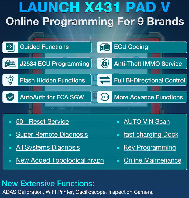
Launch X431 Pad V Pad5 Full System Professional Diagnostic Tools Support Online Coding And Programming
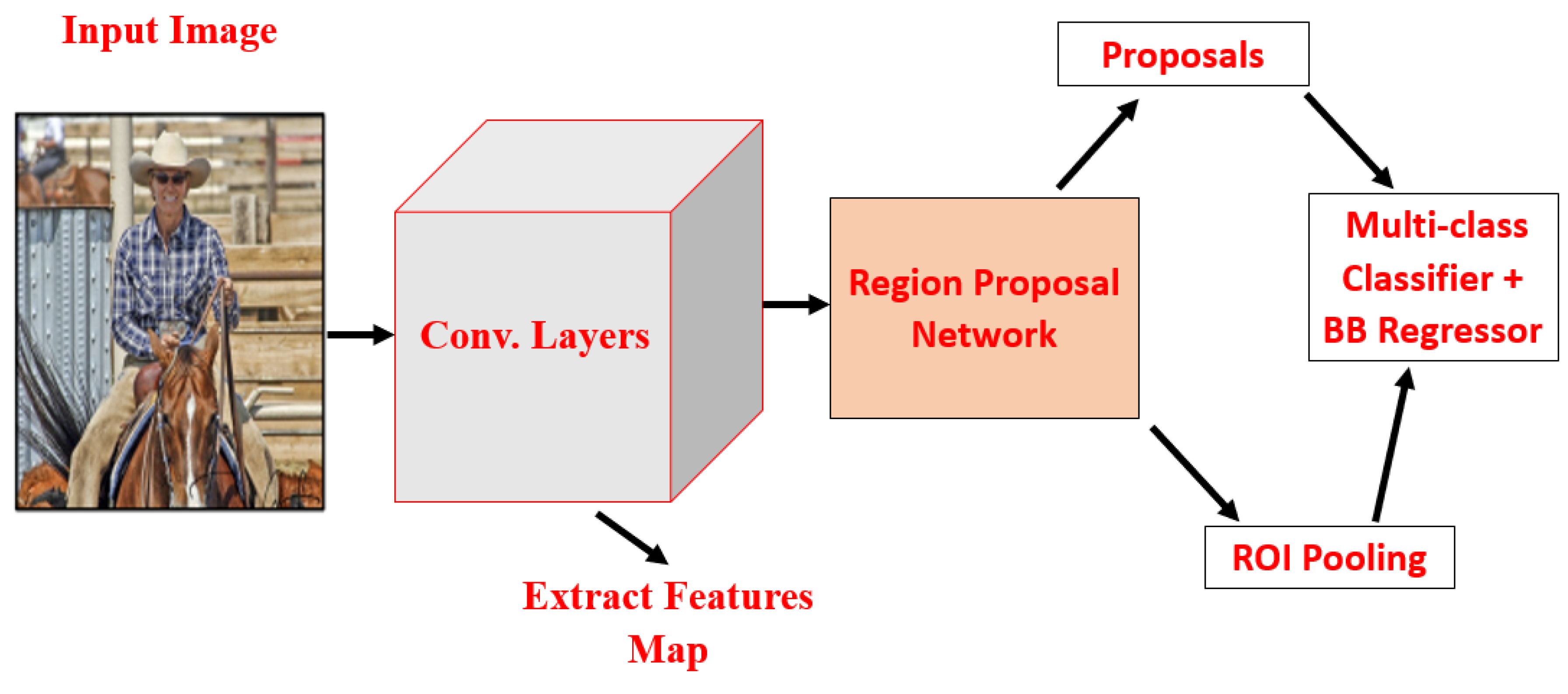
Applied Sciences Free Full Text Investigations Of Object Detection In Images Videos Using Various Deep Learning Techniques And Embedded Platforms A Comprehensive Review Html

Block Diagram Of Computer Block Diagram Computer Books Estimate Template

Block Diagram Of Computer Block Diagram Diagram Computer System
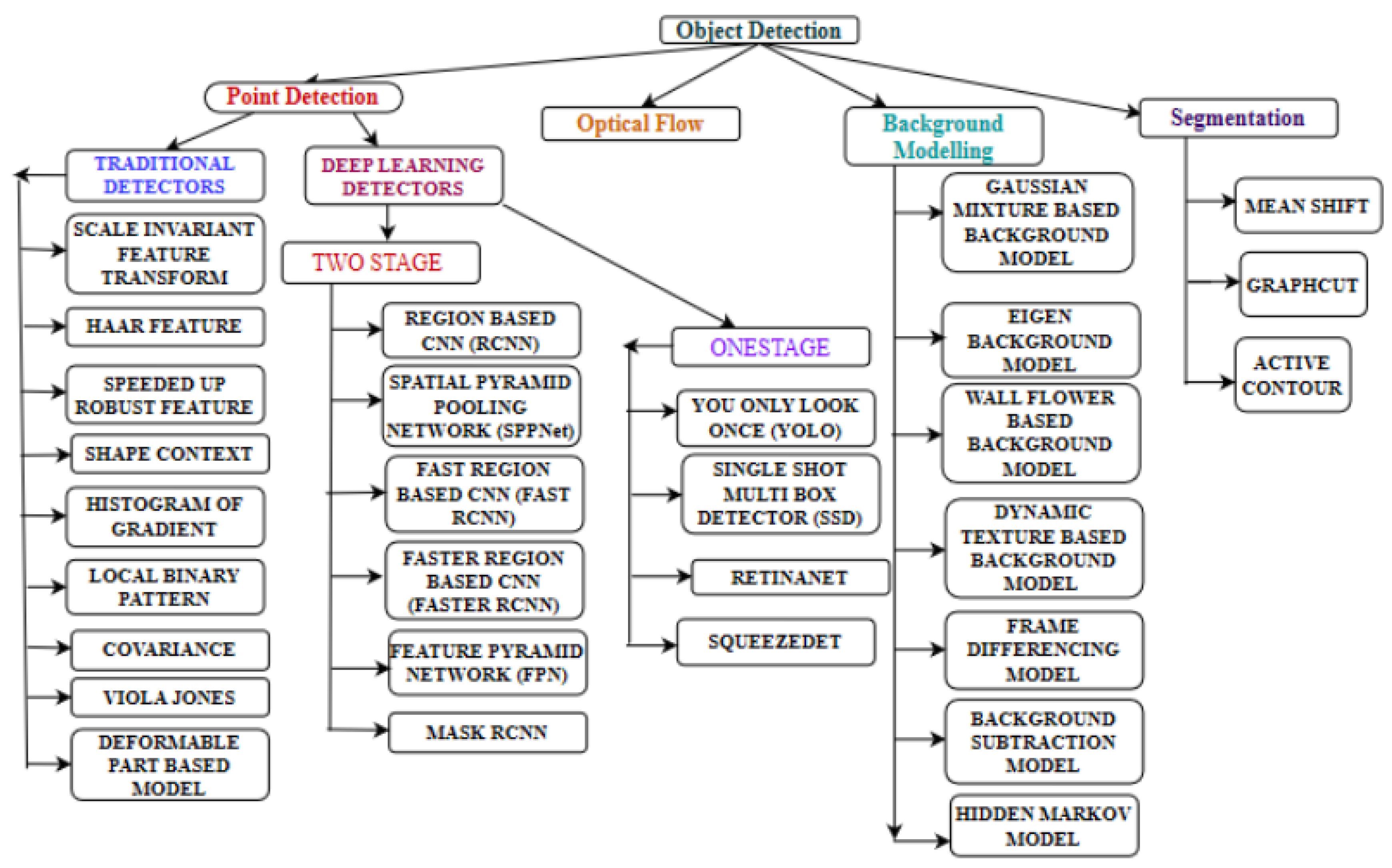
Applied Sciences Free Full Text Investigations Of Object Detection In Images Videos Using Various Deep Learning Techniques And Embedded Platforms A Comprehensive Review Html
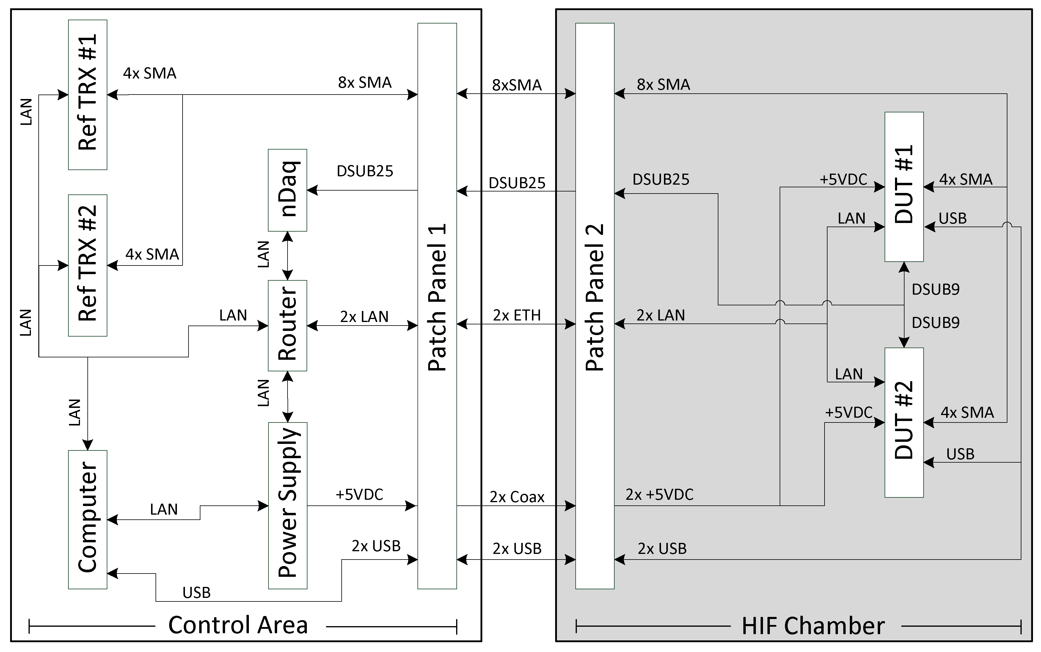
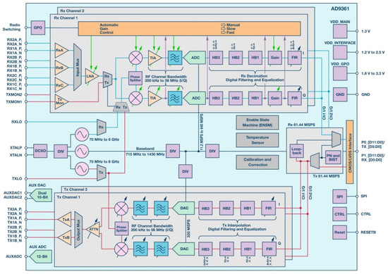
Aerospace Free Full Text Heavy Ion Induced Single Event Effects Characterization On An Rf Agile Transceiver For Flexible Multi Band Radio Systems In Newspace Avionics Html

Computer System Block Diagram With A Dma Controller And A Pic Computer Architecture Logic Design Engineering Design
Ofqmyer9wiee7m
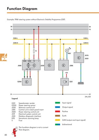
259 Ephs Electrically Powered Hydraulic Steering
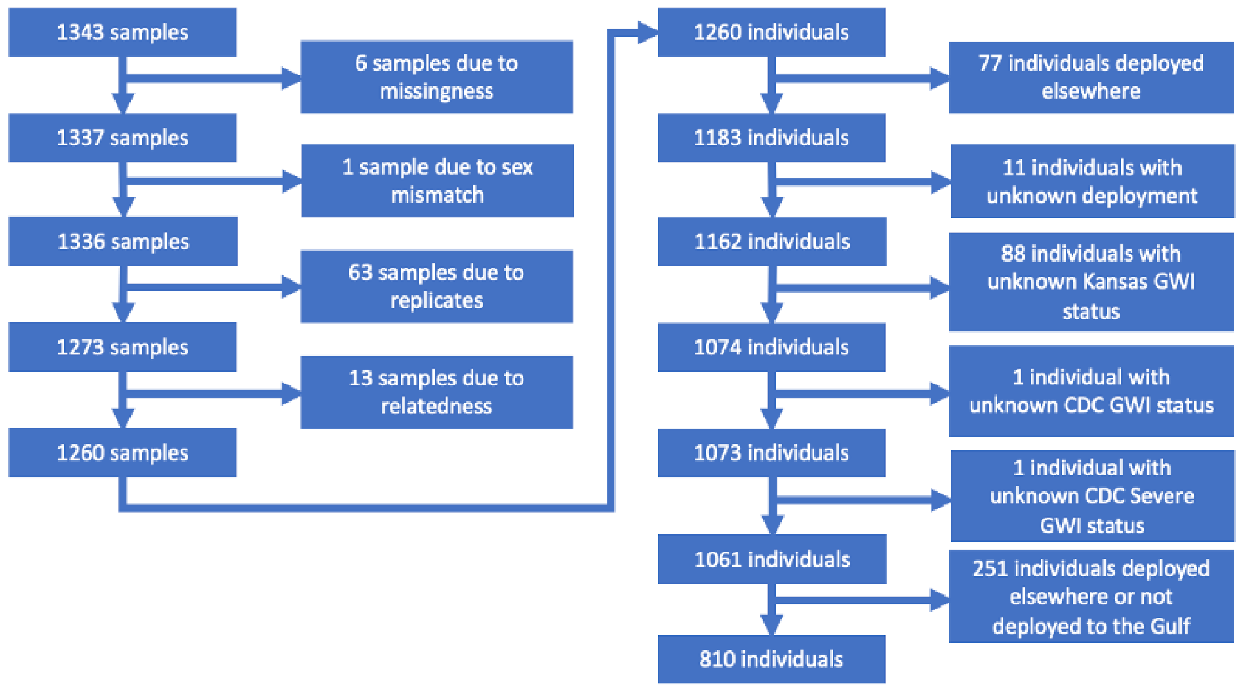
Brain Sciences Free Full Text Gene Ndash Toxicant Interactions In Gulf War Illness Differential Effects Of The Pon1 Genotype Html
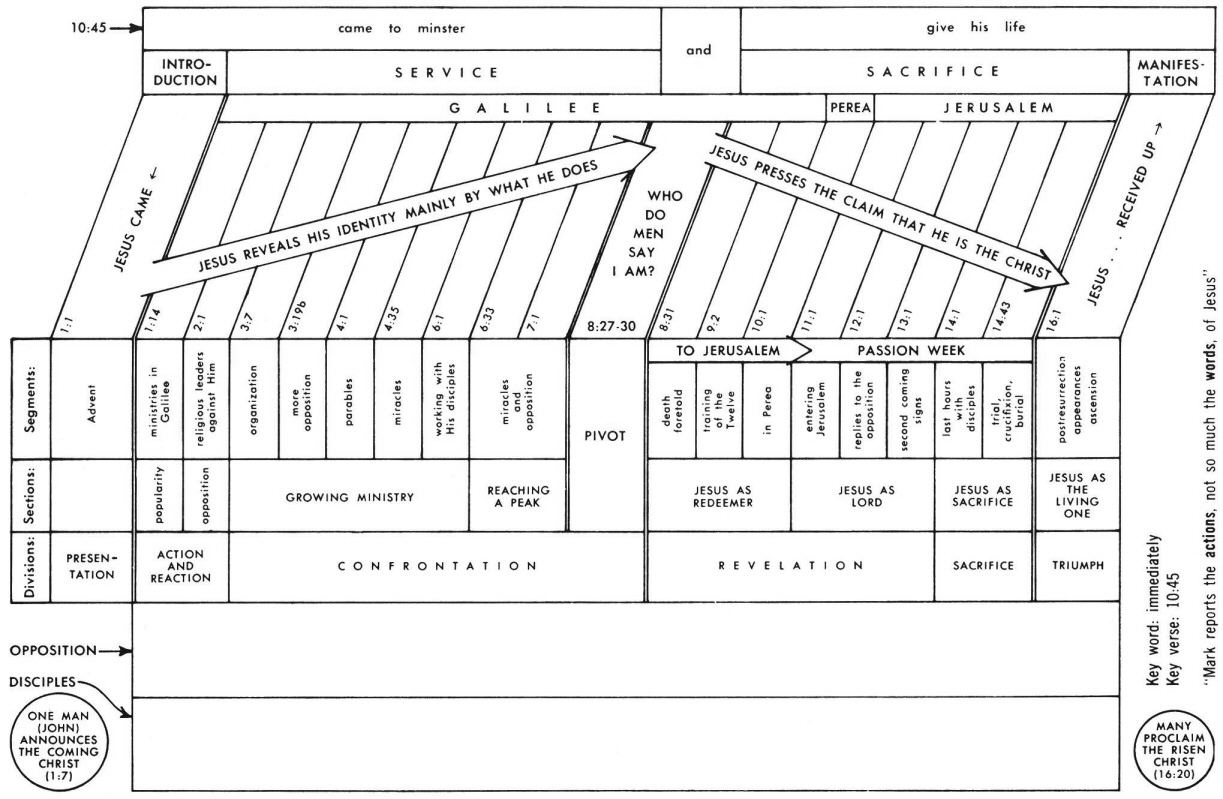
Mark 12 Commentary Precept Austin
259 Ephs Electrically Powered Hydraulic Steering
2
2
259 Ephs Electrically Powered Hydraulic Steering

Block Diagram Of Computer Block Diagram Diagram Computer
259 Ephs Electrically Powered Hydraulic Steering